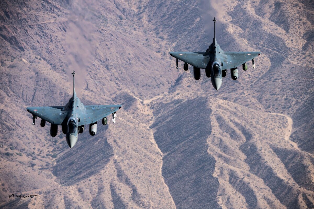
Project Conception
In 1973, Prof. Narasimha left academia for Hindustan Aeronautics Limited. He joined the Aircraft Design Bureau at a time when Indian aviation was entering an ambitious phase. Four years later, he was appointed Chief Project Coordinator, a position he held until 1979.
In the late 1970s, following a long gap in indigenous fighter design after the HF-24 and the rejection of the HF-25, GAF-1, GAF-2, ASF-300 (powered by the GTRE GTX), and HF-71/72 projects, IAF intensified its efforts to import a deep-penetration strike aircraft. This ultimately led to the import of the Jaguar in 1978, following the scrapping of the HAL ASA/HF-73(planned to be powered by M45 then RB199 and later GTX-37 variant).
During his tenure at HAL, where he was actively engaged in aircraft design and headed the HF-25 program, Prof. Narasimha advanced the idea of a new lightweight combat aircraft to eventually replace the aging MiG-21 fleet while complementing the Jaguar in service. It was he who introduced the designation “Light Combat Aircraft” (LCA) for the proposed program.
Recognizing the importance of assessing the project’s practicality, Dr. Raja Ramanna entrusted Prof. Narasimha with leading a multidisciplinary team comprising specialists from the IAF, HAL, and DRDO. The delegation visited leading European aerospace firms including BAE in the UK, MBB and Dornier in Germany, and Dassault in France to evaluate available technologies and obtain industry perspectives on the feasibility of developing such an aircraft.
Based on these evaluations and discussions between IAF and research labs, the IAF formally issued the Air Staff Target in 1981, establishing the operational requirements for the design and development of the new fighter. The IAF used to write down their requirements using brochures and aviation magazines rather than threats facing India, this was later changed when IAF started sending draft requirements to the Director of Aeronautics.
Dr. V. S. Arunachalam joined DRDO as director of DMRL in 1975 after spending long years at NAL and was appointed as DG of DRDO and SA in 1982 and was responsible for getting approval for IGMDP(Agni, Akash, Trishul, Nag, Prithvi) and LCA in 1983. Thus LCA program was formally launched in 1983 with an initial government allocation of Rs.562 cr.
Due to HAL’s lack of single-handed capacity to develop such an advanced aircraft alone, the Ministry of Defence concluded that a dedicated, autonomous special purpose vehicle was necessary. It was designed to be free from standard, rigid government procedures that normally slow down execution
The MoD established ADA as the autonomous society under DRDO funding responsible for leading the project in collaboration with various research laboratories, academic institutions, and industry partners in 1984.
When ADA was engaged with all BAE, Dassault, MBB, and Dornier, they suggested all kinds of wings from canard-deltas to conventional aft-tails, the Indian team conducted a normalization study and ultimately selected the tailless compound delta configuration for its smallest size, lowest weight, and cost effectiveness.
All companies confirmed it was possible to meet the IAF requirements incorporating specific “core” technologies, an advanced engine, FWB system, digital cockpit and composite structures, multimode radar.
Models were tested in wind tunnels to optimize the aerodynamic configuration, air intake, and control surfaces..
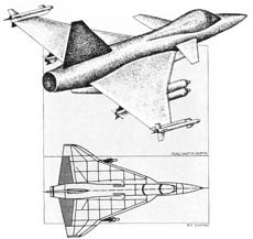
In 1986, Dr. V. S. Arunachalam, then SA, announced that ADA had selected a tailless delta-wing configuration for the LCA. Around the same period, DRDO delivered a presentation to the PM.
After nearly 25 years of limited indigenous aircraft design activity, the program aimed to rebuild India’s complete aerospace ecosystem by restoring domestic design, development, and manufacturing capabilities.
Before the LCA program was launched, India approached the USSR with a proposal to jointly develop the aircraft. To explore the possibility, a delegation from HAL and the IAF visited the Soviet Union for discussions. The Soviets, however, rejected the idea of joint development and instead offered India the option of manufacturing the MiG21 Bis, which India eventually accepted.
Soviet Defence Minister Dmitri Ustinov strongly opposed India’s pursuit of an indigenous fighter program and was particularly critical of Dr. Arunachalam. He sarcastically remarked that India would “end up flying a kite calling it LCA” and added that had Arunachalam been a Soviet official, he would have been dismissed on the spot.
Despite Ustinov’s opposition, a few senior Soviet leaders, including Aviation Minister A. S. Systov and interim Prime Minister Ivan Silayev, voiced support for India’s aviation ambitions. They even offered to send Soviet academicians to assist the Indian team.
The Indian leadership, however, viewed these proposals with caution, believing they were intended to keep India technologically dependent rather than help it achieve true self-reliance. Later, India sent Russia a request for a proposal to conduct a feasibility study for the LCA, but no response was received.
Leadership & Turmoil
However, organizational challenges emerged at an early stage. Dr. S. R. Valluri, then DG of ADA, observed that “ADA had the total responsibility but not the authority” to implement critical decisions because it depended heavily on the cooperation of organizations such as HAL and GTRE.
He argued that administrative control from New Delhi frequently overruled the judgments of the engineering teams, stating, “The ADA was set up to manage the LCA programme but it can function only through consent and consent was not forthcoming. Design was being dictated from Delhi.”
Another major controversy involved Dr. Raj Mahindra, former Director of the Design Bureau at HAL. He had led the HF-73 concept and worked closely with Dr. V. M. Ghatage, the designer of the HT-2 and HT-16. Given his extensive experience in aircraft design, Dr. Mahindra was widely regarded as one of the most qualified person to lead the LCA program, with none Indian designers possessing comparable expertise.
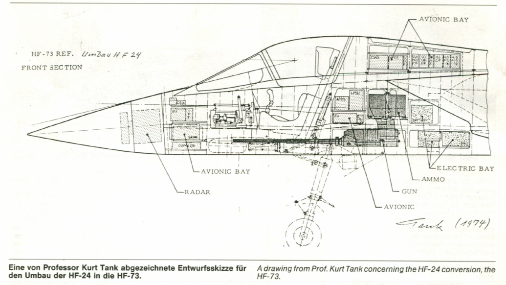
Despite this, he became the target of political criticism over his British citizenship and professional qualifications, even though these allegations had previously been investigated and dismissed by the government. Valluri believed that Mahindra was being unfairly sidelined for political reasons rather than technical considerations.
The situation reached a turning point following another round of criticism against Mahindra in Parliament in May 1985. Rather than prolong the dispute, Mahindra chose not to defend his position publicly, stating, “The LCA is bigger than the people involved. If it helps to sacrifice me, I am prepared.”
He maintained that the success of the aircraft program was more important than his personal role. When Mahindra’s contract was ultimately not renewed, Dr. Valluri resigned in protest.
Following Valluri’s departure, ADA experienced a leadership vacuum until Dr. Kota Harinarayana was appointed Program Director in 1985. Before taking charge of the LCA program, he had served as Director of ADE and had previously worked as Chief Designer at HAL Nasik.
Preliminary Design
A high-level delegation, including Kalam and Kota, visited the Paris Air Show to finalize consultancy for the PDP. Work on the PDP began in Bangalore with assistance from Dassault in 1987. Dassualt gave ADA accesss to ELFINI for airframe structural design. An IAF team was deployed at ADA during PDP to detail the various missions the LCA would perform.
During the PDP, ADA collaborated with DA of France for technical support. Although DA contributed significantly to the aerodynamic design, it was reluctant to transfer key technologies related to the FBW system and composite materials, fearing that India would eventually become self-reliant in these areas. In 1988, the PDP was completed, producing 30,000 pages of documentation that defined the aircraft’s configuration.
In late 1988, instead of accepting DA’s proposed hybrid flight control system, which combined digital controls with an analog backup, ADA decided to develop a fully digital quadruplex FBW system.
Unlike the Mirage 2000, which uses an analog FBW system, the Tejas uses a digital computer called DFCC that processes discrete sensor samples (z domain) using voting logic algorithms to control the hydraulic actuators.
Analog systems are hardwired and difficult to reprogram, while the Tejas uses a software controlled digital system that allows Indian engineers to modify the control laws easily.
The Mirage 2000, by comparison, relies on a three channel hardware layout with fixed electronic components that require physical rewiring to change the aircraft’s flight characteristics.
In a fly by wire aircraft, the pilot’s stick input is interpreted as a g demand or pitch rate demand. When the pilot moves the stick by a certain amount, the computer calculates the required control surface deflection to produce the commanded g load, regardless of the aircraft’s current speed.
The Tejas is aerodynamically unstable in the pitch axis. The DFCC has four independent digital processors that carry out synchronized computations. It receives data from rate gyros and accelerometers.
The system decouples the two axes. In response to a roll stick input, the aircraft rolls about its velocity vector while suppressing sideslip buildup during turns. This allows the pilot to initiate a turn without using the rudder pedals.
ADE was responsible for developing the DFCC hardware and the embedded software. In 1992, ADA signed a $40 million agreement with Martin Marietta (Lockheed Martin) for assistance with the FBW FCS, other candiates were Lear and Bendix. APG67 was also considered for LCA during this time.
BAE Systems also provided critical consultancy on redundancy management and system integration. While the US permitted the export of FBW hardware, it prohibited the transfer of control law technology. In June 1993, FSED Phase-I was sanctioned at a cost of Rs.2188 cr.
In 1993, the design and development of the flight control laws began, and the National Control Law Team was formed.
The team included engineers from CAIR (DRDO), ADA, HAL, ADE, and NAL. Based at the Flight Mechanics and Controls Division of NAL and led by Dr. Srinath Kumar, it developed the complex algorithms (Control Laws) that define how the aircraft responds to pilot inputs.
Indian pilots, including WGCDR Rakesh Sharma and Rajiv Kothiyal, traveled to Calspan, USA, in 1995 and 1996 to fly variable stability aircraft (Learjet NT33A and F16 VISTA). These aircraft were programmed with the LCA’s CLAW to validate how the software would behave in a real world environment before the LCA itself ever flew.
The initial CLAW code was written in FORTRAN for the simulators but was later rewritten in the Ada programming language so it could be ported to the DFCC. The DFCC was initially powered by the Intel 32 bit 80960 processor, which was later replaced by the MPC5566 PowerPC processor. The hardware and sensors were initially sourced from GE Controls.
A ground based cockpit at ADE, called the Real Time Simulator, allowed pilots to fly a mathematical model of the LCA in real time to assess handling qualities. It was used by test pilots, while an engineer in loop simulator at NAL was used for design simulation.
Following India’s nuclear tests, the US halted all collaboration. ADE engineers working in the US were sent home, and support from GE and LM was withdrawn. This forced India to indigenize the entire FCS hardware and software, adding 15 months to the schedule while building complete expertise.
The Iron Bird was established at HAL with SDR starting in 1993 and tested DFCC HW/SW v0.5 in 1996 and FCS was installed in TD1 in 1999 before first flight. This complex test rig contained all the actual aircraft hardware related to the FCS, including hydraulic actuators, onboard computers, and the landing gear. Just before the first flight of TD1, the system’s reliability was demonstrated through a rigorous 50 hour fault free test. The FCS was evaluated in autonomous mode while the stationary aircraft ran its engine from ground idle to maximum afterburner.
The aircraft features Critical Altitude Recovery, recovering aircraft if it descends below a predetermined safe altitude, Auto Low Speed Recovery, FCS takes over and performs recovery maneuver to maintain save speed, Disorientation Recovery Function, recovers the aircraft to level flight when a pilot becomes spatially disoriented.
Materials, Structures & Systems
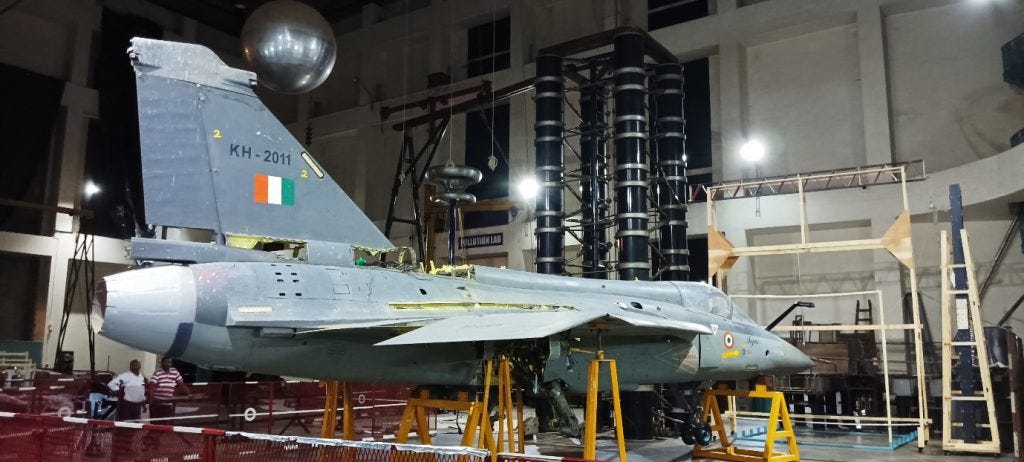
The work on artificial lightning test facility became operational in 1992 led by Prof. G.R. Nagabhushana and the tests on first aircraft began afterwards, generates impulse voltages up to 4 million volts and high currents up to 200 kiloamps across four distinct waveforms to simulate natural lightning strikes, it uses impulse capacitors to load and unload this energy. The facility is used to validate other aircrafts afterwards.
When the US banned the export of maraging steel and other actuator components, ADA partnered with VSSC and DRDL to develop indigenous alternatives. The primary servo actuators for the elevons use state of the art Direct Drive Valves. At the time, only Moog (USA) possessed this technology, but India successfully developed it indigenously at less than half the cost of imported versions. DRDL developed the electrohydraulic servo valves, which were later manufactured by CMTI in Bangalore.
The US government approved the sale of the GE404 engine in part because it saw an opportunity to reduce India’s reliance on Soviet military equipment. At the time, most of India’s defence hardware was sourced from the Soviet Union. The RB199, M54 and R25 all failed to meet the requirements for LCA.
GTRE developed an experimental engine called the GTX37-14U, which acted as a technological foundation for the Kaveri engine program. The Kaveri project received independent funding outside the LCA program, a decision that was opposed by Dr. Valluri. Apart from Kaveri development, GTRE also operates specialized test facilities for the GE404 and GE414 engines, along with an ECS facility.
These facilities were used to demonstrate various indigenous components, including the Jet Fuel Starter developed by HAL. The development of the JFS was driven partly by economic considerations, as importing such a system would have been significantly more expensive. Its main function is to rotate the main engine up to the required ignition RPM during engine start.
The development of the Aircraft Mounted Accessory Gearbox (AMAGB) was assigned to CVRDE, which collaborated with IIT Madras for its design. Manufacturing support was provided by HAL’s Foundry division and the HVF, Avadi for producing this important component of the LCA Tejas’s secondary power system.
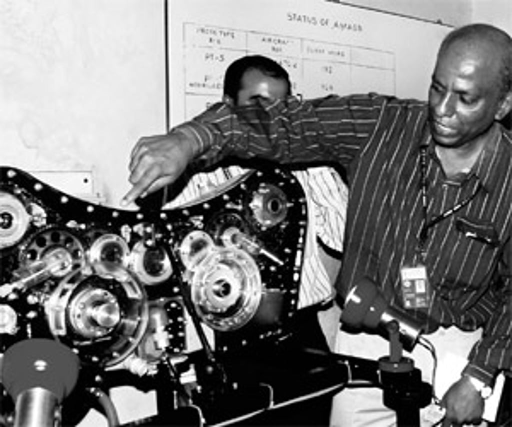
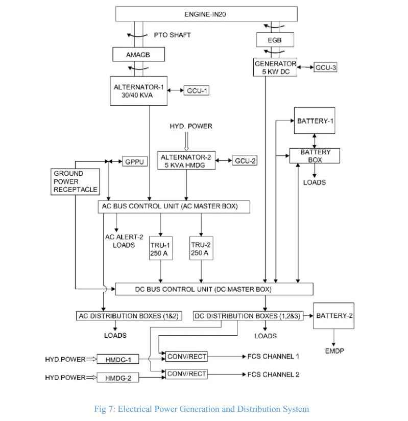
The AMAGB is powered through a PTO shaft connected to a drive pad on the engine gearbox. Its primary role is to operate two hydraulic pumps and an integrated drive generator (Alternator 1). The AMAGB completed 1,000 hours of endurance testing and accumulated more than 6,000 flying hours in indigenous versions, proving its reliability.
The main power sources include a 30/40 KVA, 115/200V, 3-phase AC IDGC and two 250-amp TRUs providing 28V DC. In addition, there is a 0.3550 KVA HMDG system providing 28V output through a rectifier converter unit. Standby power comes from a 5 KVA, 115/200V, 400Hz, 3-phase HMDG and a 5 KW, 28V DC generator. Emergency power is supplied by two 44Ah, 24V Nickel-Cadmium batteries from HBL.
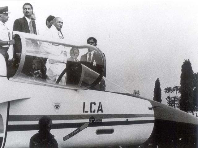
In 1995, the wings were mated with the fuselage, and TD1 was rolled out on November 17th, as aircraft KH2001 in a ceremony attended by PM Narasimha Rao.
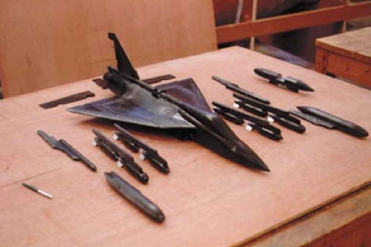
During the 1990s, technology denial forced India to develop critical capabilities domestically. As a result, CSIR NAL was tasked with developing advanced aerostructures, composite materials, and large autoclaves capable of fabricating the LCA’s wings. NAL was also involved in making of wind tunnel models using composites. This technology was then transferred to HAL and TASL with installation of large autoclaves at HAL.
India’s National Wing Team was formed under the leadership of Dr. K. N. Raju, bringing together experts from HAL, ADA, and NAL. Even before work on the LCA began, NAL had demonstrated its computing capability by developing India’s first parallel computer, Flosolver, under Prof. Narasimha. The machine achieved almost three times the computing performance of the Univac systems that were in use at the time.
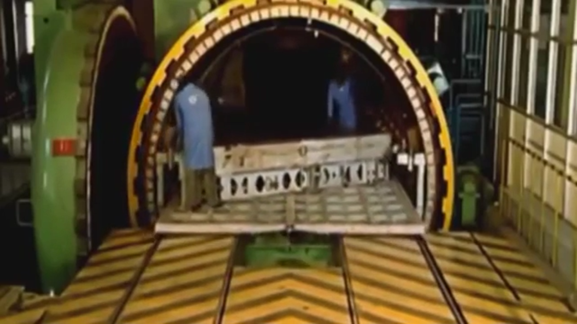
By 1995, HAL had received the first completed wings and rudders for the aircraft. The wing skins for TD1 were manufactured by Alenia in Italy, while later prototypes, especially PV1, made extensive use of composite structures. TD1 and TD2, however, continued with a metallic fuselage. DRDL developed an indigenous Kevlar based three dimensional contoured radome. The kevlar radome was shelved due to it choking the radar performance and Cobham was contracted to supply quartz radome, delay stalled the FOC by a year.
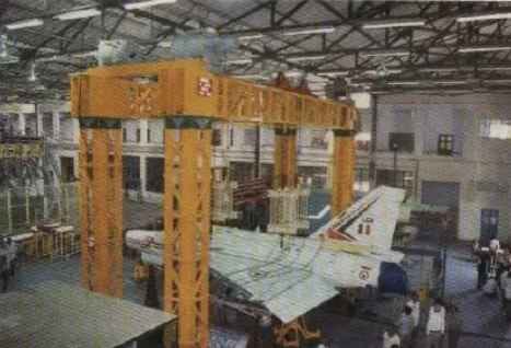
HAL started Structural testing with to validate airframe integrity, vibration limits, and flight control safety.
CSIO designed and built India’s first indigenous HUD Mk1 after the United Kingdom, the United States, France, and Israel declined to supply the technology. The same HUD design was later integrated into the NLCA, Su30MKI, HJT, IJT, Hawk I, and Do228, the 18 kg HUD come with NVD capability.
BARC developed the Shape Memory Alloy rings required for the program, while ADA established a dedicated production facility for these alloys in Bangalore.
ARDC designed the landing gear by drawing on experience gained from the HJT16 and HF24 programs. When export restrictions from the United States blocked access to high strength steel, MIDHANI successfully produced the material domestically. HAL’s Foundry and Forge Division manufactured the individual components, after which ARDC carried out the final assembly.
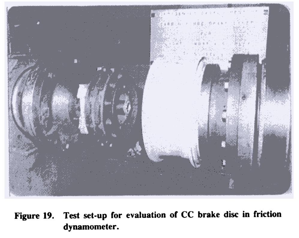
Unlike the MiG program, where conventional iron brake pads were sufficient, the LCA demanded advanced carbon-carbon brake pads capable of delivering nearly four times the service life. HAL partnered with DRDL, which had already developed expertise in carbon-carbon composites through the Agni missile program, to produce this braking system.
DRDL developed multidirectional fibre preforms, including 3-D, 4-D, 5-D and 6-D structures. The advantage was that the fibres could be arranged in different directions depending on the loads the final component had to withstand.
DRDL developed the discs using different fibre architectures and tested them through 50 dynamometer runsm 45 normal stops at 21.2 MJ and 5 overload stops at 29.8 MJ simulated landing energy. It was later handed over to ASL/HTCC.
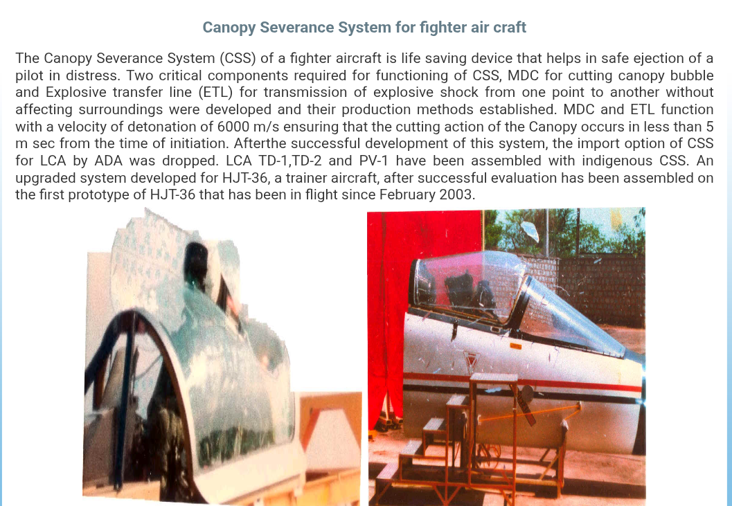
ARDE and HEMRL in Pune jointly designed the Canopy Severance System for the aircraft. Earlier ejection systems relied on completely jettisoning the canopy, a process that typically required more than 1400 milliseconds. The LCA adopted a much faster approach that fractures the acrylic canopy within 5 to 20 milliseconds, allowing the 20 deg inclined Mk16 zero zero ejection seat to exit the cockpit safely. Once ejection is initiated, a Pressure Actuated Initiator generates a gas driven shockwave that travels through Explosive Transfer Lines at approximately 6000 m/s. The shockwave reaches a Shaped Miniature Detonating Cord installed around the canopy, activating a linear cutting charge that shatters the canopy almost instantly and clears the escape path.
The first mission computer developed for the LCA was powered by Intel’s 386 processor. At the time of its selection in 1986, it represented one of the most capable processors available for use in the Technology Demonstrator program.
A team led by Dr. B. G. Prakash created AUTOLAY, a software suite that automated the design, structural analysis, and quality verification of the Tejas airframe, whose surface was nearly 90 percent composite. The software gained international recognition and was later adopted by organizations including Airbus for the A350 and A380 programs, Boeing, Hughes Corporation, and Antonov.
LCA was not made to be a stealth aircraft, even then it features a Y intake design which hides the compressor/face of the engine, with 90% of surface area covered with composites (low dielectric loss), LCA is a small aircraft, flush air data probes, canopy coating, airframe applied with RAM paint and smokeless F404 engines, IISc made RCS prediction techniques for LCA and an open-test range for measuring RCS of full scale aircraft was developed.
IAF asked for a new canopy in the FOC aircrafts. An upgrade from a 16mm thick canopy built to survive 20gm bird strikes, to a 24mm canopy that can take a 40gm bird hit. A drogue light was added for night IFR capabilities.
Radar
The original plan was for the LCA to use the PS 05 radar from the Gripen. This approach was later abandoned, and LRDE initiated the development of an indigenous Multimode Radar. The radar made its first flight aboard a modified Avro-748 flying testbed in 1997. It was a mechanically scanned pulse Doppler radar equipped with a flat plate slotted planar array antenna.
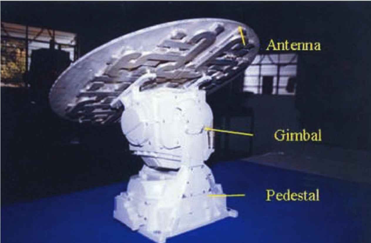
BARC and ECIL developed the hydraulic and servo driven two axis gimbal that physically rotated and tilted the antenna during scanning. BARC also designed the servo control logic, and stabilization algorithms that compensated for rapid aircraft motion, allowing the mechanically scanned antenna to remain accurately locked onto its target.
Due to delay in MMR a hybrid solution was taken where India kept the 650mm slotted planar array antenna and scannar with core software, receiver modules, and computational processor of EL/M-2032.
Work on the Uttam AESA radar was started during this time, to replace the EL/M-2032 eventually. The Uttam version 1 started as a TD with 736 GaAs TRMs then version 2 with 912 GaAs TRMs. Finally, an order of 97 units of Uttam is placed. These 97 units will come equipped with GaN based TRMs with peak power of 9.12 kW.
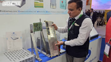
The system transitioned from a 32-channel plank architecture (8 QTRMs × 4 channels) to a next-generation 64-channel tile architecture (8×8 array face). This upgrade doubles the active radar channels while shrinking the overall physical hardware size to just 1/3rd of the original footprint.
Flight Testing
In 1994 National Flight Test Centre is established under Air Marshal Phillip Rajkumar at HAL airport in Bangalore to provide integrated team of test pilots solely for LCA. The core team included pilots like WGCDR Rakesh Sharma (India’s first cosmonaut), WGCDR Rajiv Kothiyal, and SL Baldev Singh. They also chair the Flight Readiness Review Board, which clears systems for safety before clearing prototypes for flight.
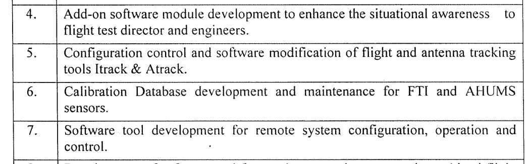
NFTC also developed systems to track and analyze the aircraft during flight. A dedicated control center was established to monitor flight activities, with engineers continuously observing critical parameters. Telemetry stations were set up to support weapons trials, along with the iTrack software for streaming data from the aircraft’s telemetry sensors. The system provides the control center with the aircraft’s exact position, 3D trajectory, and safety envelope information. They were also tasked with test points, drafting flight schedules and making protocol documents.
Atrack uses high gain ground telemetry antennas that maintain a continuous link with the aircraft, keeping track of its position during high G maneuvers, supersonic flights, and steep dives while preventing the loss of critical flight data.
NFTC test pilots provided real-time feedback to ADA on cockpit design, avionics, and CLAW to advance LCA development. One of the examples being, the LCA lacked a redundant flight path sensor for the safety-critical ALSR routine embedded in the FCS. This missing hardware threatened massive project delays and high costs to achieve IOC.
WGCDR Raveendran resolved the issue by using his EPNER thesis to suggest a math algorithm that cleanly calculated the missing data using existing air probes. This virtual sensor bypassed the need for secondary hardware, fixed the CLAW deadlock, and successfully cleared the jet for IOC
Engineers also developed a six kilogram unmanned scale model of the LCA. Flight testing began in 1998 to evaluate handling qualities, flight characteristics, and control system performance before these results were incorporated into the full scale aircraft.
In 1998, the Kaveri engine completed its first engine run, and TD2 was rolled out later that year. Brake Dynamometer Facility came online in 1999. TD1 entered low speed taxi trials in 1999, and by December 2000 the Flight Readiness Review Board cleared it for its maiden flight.
During the taxi trials conducted in late 2000, the test envelope expanded rapidly from about 50 km/h to over 260 km/h. In the final high speed run, WGCDR Rajiv Kothiyal accelerated the aircraft to around 250 km/h, lifted the nose wheel in a controlled manner to verify handling characteristics, and then brought the aircraft to a stop using the brake parachute.
Ahead of final session on December 24, 2000 of FRRB, ACM Anil Tipnis expressed hesitation about attending the meeting. Tipnis informed Rajkumar that his advisers had told him not to attend the FRRB, because his presence would be interpreted as official IAF support for the LCA program. AM Rajkumar told Tipnis, “Sir, the LCA is being built only for the Indian Air Force and not for an enemy air force.” Tipnis ultimately chose to ignore his advisers and attended the final session. This section of IAF being the issue to indigenous weapons development.
On 4 January 2001, Air Marshal Rajkumar signed Form 1090, the official Release for Flight, becoming the only Air Marshal to personally authorize the maiden flight of an Indian combat aircraft. At 10:18 AM, WGCDR Rajiv Kothiyal lifted TD1 into the air for its historic first flight.
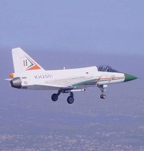
Throughout the sortie, the aircraft transmitted nearly 1,200 telemetry parameters to the NFTC control centre, although the telemetry link was lost shortly after takeoff. Two Mirage 2000 chase aircraft accompanied TD1 and relayed flight observations and critical data. WGCDR Nambiar flew in close formation, visually inspected the aircraft, and confirmed that the flight could safely continue. The 18 minute sortie included speed and air data calibration checks, while the entire event was recorded on film by G/C Krishna.
The maiden flight was carried out in fixed gain mode, where the aircraft’s flight control software was manually restricted to keep the flight envelope conservative. During the second flight, WGCDR Kothiyal retracted the landing gear for the first time. By its fourth sortie, the LCA made its public appearance at Aero India 2001.
TD2 joined the flight test programme in 2002, with WGCDR Tarun Banerjee flying the aircraft. During the early phase of testing, both aircraft operated under strict flight envelope limits. They were restricted to bank angles of 60 degrees, basic turning manoeuvres, and a maximum load factor of 4G.
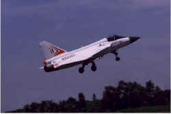
The software continued to operate in fixed gain mode with conservative limits to ensure safe expansion of the flight envelope. In 2003, PM Vajpayee officially named the aircraft Tejas, and later that year TD1 and TD2 completed their first formation flight.
During the sanctions period, TD1 and TD2 were cannibalized to supply parts for the Prototype Vehicles. It reached Mach 1.08 for its 33rd flight piloted by WGCDR Vikram Singh, during it’s 34th flight TD1 flown by then G/C RKS Bhadauria reached Mach 1.15 at 11 km altitude.
In 2003, PV1 made its first flight, piloted by S/L Suneet Krishna. PV1 was the first aircraft to feature a front and centre composite fuselage, allowing the LCA to achieve nearly 90 percent composite surface area. PV1 weight was reduced by 746 kg from TD1 with less parts. Internal fuel capacity of 2458 kg, 580 kg in each wing tanks with total 7 internal fuel tanks. Mk1 will also undergo MAFT testing at ARDC over 8-9 years that will qualify LCA to its full-service life.
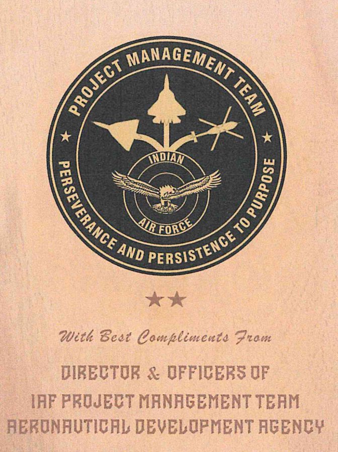
It was during this time that Project Management Team of the IAF was sent to ADA. The IAF remained uninterested till then to take control of LCA.
PV2 made its first flight on 1 December 2005 with a new fiberglass cockpit, a higher percentage of composite structures, and an improved CLAWS. Several components were removed from PV1 for flight of PV2. During this period, there were also suggestions that the programme should be handed over to HAL. 6G CLAWS were opened in Aero India 2007. PV2 soon flew for the first time with “Litening” pod flown by WGCDR N Tiwari.
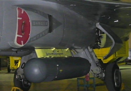
PV1 soon flew with two 800 ltr drop tanks and test flight lasted about 45 min. It didn’t take fuel from it yet, only validated the CLAWS and SMS. Later in 2008 it flew with fuel from drop tanks with flight lasting about 1 hr 24 min with fuel left. In this year, LSP-2, used F404-IN20 engine instead of GE404-F2J3(81 kN) of previous aircrafts, it came with increased MTBO, FADEC and 85 kN of thrust, also new ejection seat, MB 16LG.
The first trainer of LCA(LT-5201/PV-5) took its first flight. The control laws, OFP V8000, were made for the trainer, canopy was redesigned, internal fuel was removed. The aircraft was to be upgraded with IFR after induction. Two technology demonstrators TD-1(KH2001) and TD-2(KH2002) then PV1(KH2003) till PV4 and two, PV-5(KH-T2009) and PV-6(KH-T2010) trainers then LSP started with LSP-1(KH2011) till LSP-8(KH2018). KH being tribute to Dr. Kota Harinarayana. Then LA series with IOC, LA-5001 to LA-5016 in service with No. 45 Squadron, and FOC, LA-5021 to LA-5032 in service with No. 18 Squadron.
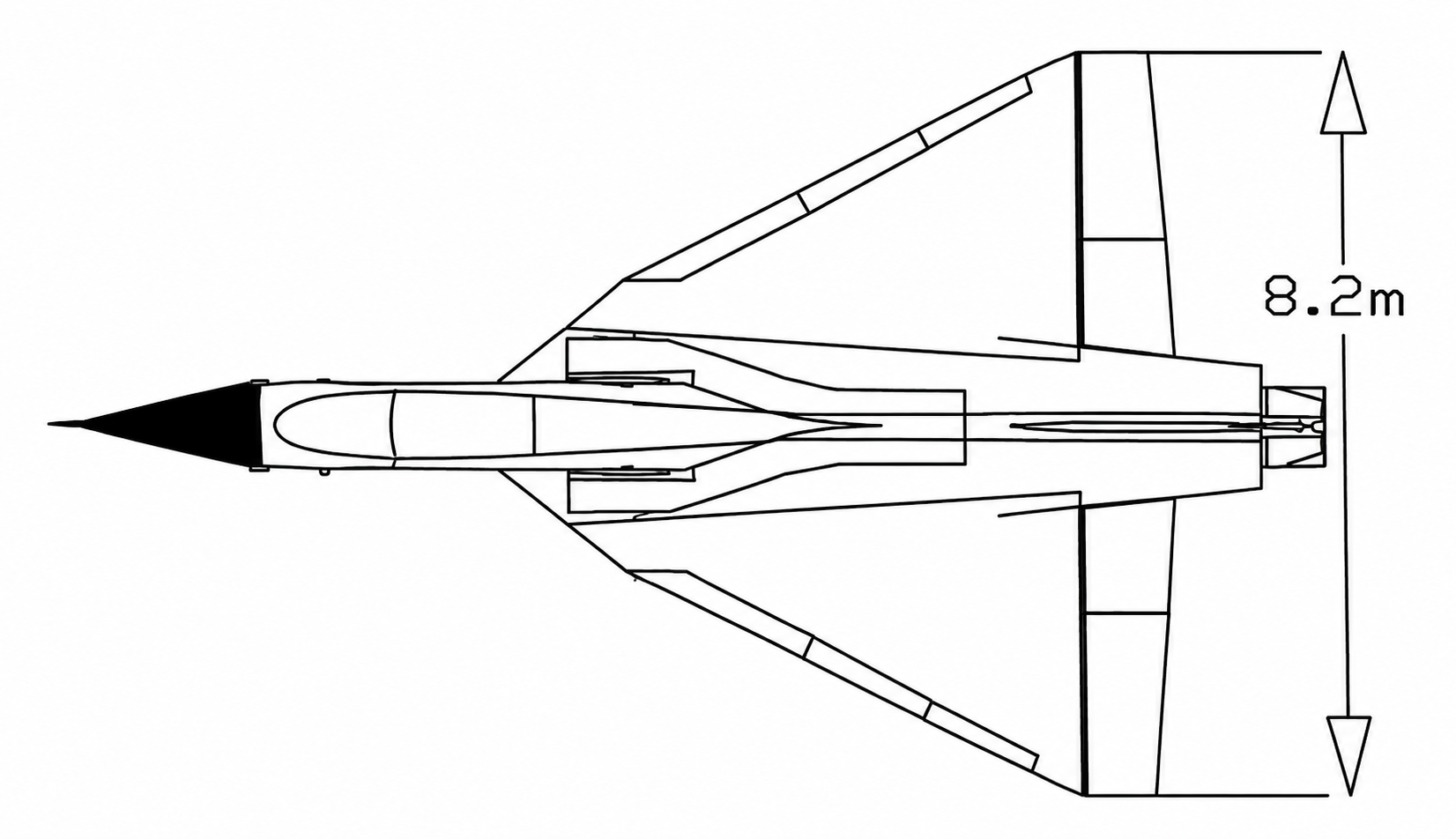
LCA achieved 26 deg AoA and pushed to 8G by test pilots, with wing area of 38.4 m, width of 8.2m. Trailing edge is 4 deg forward, leading edge 50 deg backward, it also flew with AUW more than 14 tons, also has shown vertical rise (TWR > 1), ITR of 30 deg/s, sustained turn rate of 16 deg/s and 350m radius turn with A2A loadout.
During Bahrain Air Show in 2016, LCA FCS was updated by Indian engineers to unlock full 8G maneuverability for display. For ramping up production GoI sanctioned Rs.1381.04 Cr in 2017 from 8 to 16.
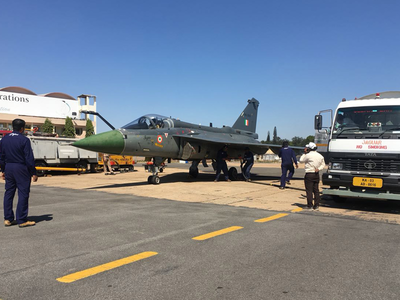
Tejas flew to Leh for hot and high and cold soke testing, where engine and ECS were tested along with JSF where it did 3 startup at -15 deg C at 10,682 ft. Hot weather trials were conducted separately in Jaisalmer, Uttarlai, and Nagpur with temp upto 48 deg C. Later same was done with LCA Trainer with full loadout.
LSP8 underwent Hot refueling trails, and was the first aircraft in IAF with this capability. It cuts down refueling time by half and significantly reduces the overall turn-around time during combat situations.
Weapons Integration
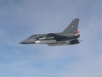
The LCA uses a Stores Management System integrated with the mission computer to control all weapons, sensor pods, and drop tanks. Its fully digital architecture allows the integration of Indian, Western, and Russian weapons. Once a weapon is selected, the OAC calculates the targeting solution and generates the firing command.
The command is then sent to the Stores Interface Box, which translates it according to the communication protocol required by the selected weapon. It is then forwarded to the Pylon Interface Box inside the wing pylon, which communicates with the store and carries out the required action. The Stores Interface Box also directly manages the GSh 23L, CMDS, and chaff systems.
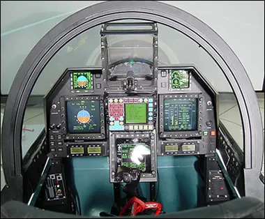
From PV2 onwards, the LCA switched to the OAC. With PV3 getting the third MFD and OAA. Three 5x5in AMLCDs manufactured by BEL, with left MFD for stores, central for radar, maps etc. and right for performance.
GSh-23 cannon was integrated on LSP-7 and ground-fired successfully, but trials revealed further issues that had to be addressed before full operational clearance, including airframe vibration, gun-gas ingestion near the engine intake, weapon alignment/calibration and possible structural effects from prolonged firing.
The gun therefore remained outside the completed FOC capability in 2019. LSP-7 was later sent to HAL Nashik, where renewed butt-firing, calibration and air-to-air firing trials were conducted to qualify the cannon under actual flight conditions.
The process of integration starts with user stating the requirements, establishing performance parameters then updating store families, updating the FCS to handle change in CoG and structural vibrations during weapons release after which ground testing in carried out in dynamic weapons integration rig and iron bird and structural coupling tests. After which weapon is mounted on the aircraft, and ground tests and taxi trails are conducted. Flight tests are conducted in fixed gain mode and weapons firing tests at max parameters are conducted.
Feasibility studies for Astra Mk-1 BVRAAM for LCA were started in 90s, it was showcased in 98 and, the early missiles were funded by DRDO and test fired three times in 2003 from a ground launcher, it had a range of 40 km, and it got sanctioned in 2004. The missile was redesigned and range increased to 60 km and tested from Su30MKI in 2014, then 80 km and then 110 km in production in 2019 and 160 km in 2025 for which work was started 3-4 years before.
The IAF revised its weapon requirements several times during the programme. The change from the R60 to the R73E required a redesign of the integral wing, delaying the programme by around 14 months. Requirements such as M62 bombs and CMDS were also added. The IAF later replaced the R60 CCM with the R73E and required its integration with the MMR and HMDS for IOC by December 2009, a requirement that was not part of the original 1985 ASR.
The R73E is a third-generation CCM capable of head on engagements even against aircraft using afterburners. It uses a proximity fuse, while a nitrogen bottle cools the seeker head. It entered service in 1984 with Mig29.
Integration began with ground testing. During flight, the airframe experiences vibrations, and if these are incorrectly interpreted by the flight control computers, they can command unwanted control inputs and potentially cause loss of control. To prevent this, filters were added to the flight control software to reject these vibration signatures.
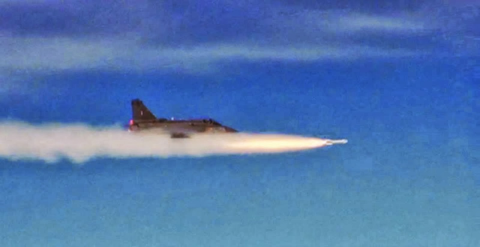
The R73E plume contains phosphorus, raising concerns that it could disrupt airflow into the engine and cause engine failure. The hot exhaust plume could also damage the LCA’s composite wings. To study this, the team removed the missile’s warhead, electronics, and other systems, leaving only the rocket motor, which was mounted on a test bed at DRDL. The plume was recorded for six seconds and produced around 12 kN of thrust. The studies confirmed that the missile posed no major risk to the aircraft.
Flight testing then began with dummy missiles to map the aircraft’s characteristics. The first unguided firing of the R73E was carried out by W/C Harish Nayani over Goa. Flying from PV1 after taking off from INS Hansa, he launched the missile at an altitude of 7 km and a speed of Mach 0.6, while Sea Harriers monitored the trial. It tested separation of the missile, effects on air intake, SMS, and effects of missile plume.
In 2010 LCA completed a critical 1,200 ltr drop tank jettison trial, it was conducted over the air-to-ground range at Challakare by NFTC and proved safe, clean separation of auxiliary fuel tanks.
In 2013, R73 was tested against a target being towed by PTA Lakshya, launched from Indian Navy ship, it was done first time using on board MMR rather than HMDS.
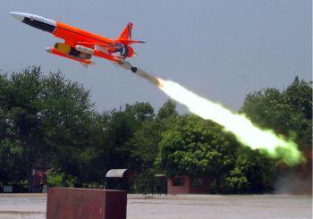
A2G weapons were tested during 2009 Aero India with a low profile approach, bomb drops were conducted on Anjediva Island. G/C Ritu Tyagi later piloted the Mk1 with public display for live A2G and AAM firings during Iron First. LCA also underwent engine relight tests with G/C RR Tyagi flying LSP7 chased by Hawk at 30,000 ft brought throttle down to 0, making aircraft lose power and pulling it again to relight the engine.
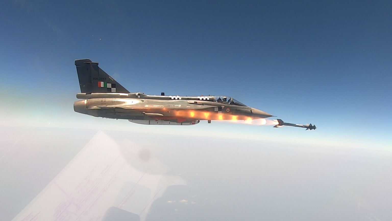
Due to LCA having Israeli radar the Derby was chosen as BVR until Astra was ready, with LSP-7 in 2016 carrying out unguided firing over Jamnagar. In 2017 the Derby was fired in LOAL mode using radar guidanace, the target was a MAT. The Python 5 was fired finally in 2021 after having issues with it, it was quickly replaced with ASRAAM with lot less control surfaces. In 2023 LSP-7 fired Astra from 20,000 ft. ASRAAM was integrated in 2025.
Mk1A
HAL pitched Mk1A to the IAF in 2015 due to shortage of manpower to work on Mk2 and delays it will cause. The work on LCA Mk1A in 2015 with disussions between ADA, HAL and IAF since LCA Mk2 was to take time in development and design change, that went from 15-ton MTOW to 17.5 ton over time. SoP-18 established the blueprint for Mk1A, upgrade over FOC with AESA radar, EW suite, AAR, easier maintainability, Dash 5 HMDS, 14 min turnaround time, redesigned canopy, repositioned LRUs, quick access panels, HAL used it expertise to ease LCA for manufacturing.
After push from Parrikar the IAF sent a proposal for 83 Mk1A aircrafts. Under HAL, Mk1A was chosen to field ELM-2052, a precondition to Jaguar upgrade where ELM was assured of one more fighter from IAF inventory to field this radar. Mk1 was to have an internal jammer but due to space issues, the plan was dropped, EL/L-8222WB AESA jammer was chosen. PowerPC MPC5566 based DFCC was flown in 2024, for easier maintenance and higher processing power, with ARINC connectors to allow computer to be swaped out and team switching to C from Ada for future due to shortage of Ada programmers.
Mk1A has repositioned digital RWR, spice bombs, Astra SIM modes, Meteor and Astra-1/2/3, BrahMos-NG, SMFDs, ASPJ, EW Suite. It will get SRK suite, an evolution over D29 to work with Uttam AESA and DRDO ASPJ and RWR(2 to 18 GHz). The 16 channel GaN based ASPJ will be a major breakthrough when certified, with 5-18 GHz band instead of standard 6-18 GHz, it is also a product of embargo where MMICs were denied.
The LCA program was about replacing the Mig-21 and other aircrafts in IAF service which it will eventually with economics of scale taking place, the engine issue is there with Kaveri failing to meet the requirements, the LCA managed to build the lost ecosystem that was ended with scrapping of HF-73, MSMEs, Academia, research labs, testing facilites, certification knowledge, production techniques, design knowledge to be applied to Mk2 and AMCA which will use Model Based Definition, jigless assembly. The best of class composites, when FGFA was going on, Indian side was to be responsible for composites of Su57 due to our expertise in them.
Calling LCA three legged Cheetah is a disrespect to not just 1000s of engineers who worked on it but also to dozens of Test Pilots who risked their lives for the program.
Footnotes
- Raj Mahindra, Lost Decade.
- India Today, “India’s futuristic LCA project faces barriers of bureaucratic hassles, serious differences,” 1986.
- K.G. Narayanan & P.S. Krishnan, Digital Flight Control Systems for Practicing Engineers, DRDO, 2020.
- Shyam Chetty & Girish Deodhare, Design and Development of Flight Control Laws for LCA.
- Kota Harinarayana, Renaissance in Indian Aviation: The Epic Journey of India’s Light Combat Aircraft, 2026.
- Air Marshal Philip Rajkumar (Retd.), The Tejas Story.