A few old photos & diagrams from DRDO's Scramjet test stand.
.png")
The test stand has a multi-strut based supersonic combustor. The schematic of the combustor is shown below:
.png")
As the schematic shows the combustor is divided into multiple sections each housing a symmetric array of struts. According to position the struts are given a Stage number. A strut is an angular device often used in aviation industry with the intention of bifurcating stream lines. Depending on the shape & size struts may be used to control turbulences, generate lift or drag etc.
In this case however struts are used as fuel injectors. So the struts will slice the supersonic stream inside the combustor & inject fuel into the stream. Thus these struts will be subjected to incredibly high pressures & temperatures during the operation of the scramjet. This posed a challenge of materials, an appropriate alloy had to be chosen for making the struts.
This is how DRDO described the material selection for a series of ground tests of the scramjet engine :
.png")
The engine was lit for 20 seconds using refined Kerosene as fuel & with Mach 2 as combustor entry speed. Remember this is from a paper published a few years back. The problems described here are solved. DRDO eventually settled on Nimonic C-263 alloy to make the struts. The alloy was further modified by DMRL before undertaking the flight test that last year. The combustor casing was made of an unnamed Nickel-based alloy.
The design of the struts were also a challenge. The struts faced very different pressures & temperatures depending on where they were placed. The Stage-I struts were subjected to a cooler undisturbed flow of air. Thus they did not need any additional cooling.
STAGE-I strut :
.png")
The Stage-I strut is the only un-cooled strut in the entire configuration. The leading edge radius is R1.5 with θwd =12°. A total of 110 injector holes are used, each of 0.5 mm diameter. The fuel injection happens in the direction perpendicular to the flow.
STAGE-II/III struts :
.png")
Stage-II & III struts have a common design. These are cooled struts with two-passages for the fuel to flow through them which act as a heat exchanger. The cooling is done by the Kerosene fuel itself. These struts also have 110 injector holes of 0.5 mm size. Perpendicular fuel injection pattern has been employed to inject the fuel.
Here is a photo of one of the Stage-II after the 20 sec ground tests :
.png")
The photo shows that the nose of the strut has undergone a significant degree of ablation. The strut survived the tests & remained thermo-structurally safe to be used for longer duration tests.
During later stages of ground tests when the size of the scramjet combustor was increased there was another stage of struts that was included.
STAGE-IV struts :
.png")
This is the newest addition to the family & carries the most complex design of them all. The trailing edge of the strut features a series of alternating wedges. The injection hole are made on the trailing edge, thus the fuel injection happens in the direction of the flow. Though exact numbers are unknown, the number of fuel injection holes are less than Stage-II/III.
Here is the general flow path configuration used for both simulations and ground testing :
.png")
The revised arrangement of the struts :
.png")
A new middle wall was introduced which allowed increasing the number of struts. Notice how there are 2 Stage-I struts instead of one. Increased fuel injection is needed for increasing the speed of the vehicle but it comes with problems. Increased number of struts & more injected fuel means significantly higher temperatures. Thus these modifications are introduced only after some breakthroughs have been made on the materials research side.
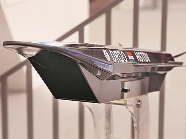
Here is the newer wind tunnel test model :
.png")


 www.onmanorama.com